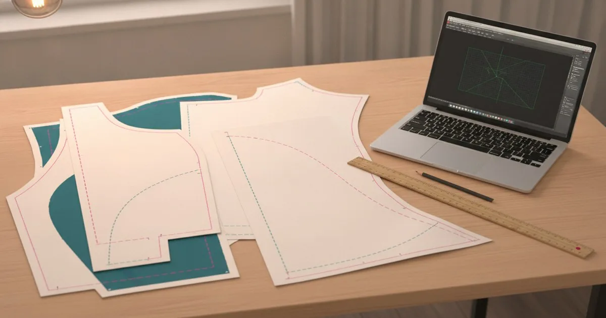
Getting a DXF pattern file out of your CAD software is only half the job. The other half is making sure the cutting room at the other end can open it, nest it, and cut from it without calling you to fix something. This guide walks you through the full export-and-handover workflow: the right layer settings, a naming convention that survives email and FTP, and a pre-send checklist that catches the most common errors before they become a sampling delay.
Key takeaways
- DXF files for garment production must follow the AAMA/ASTM layer convention so nesting software can distinguish cut lines from sew lines and notches automatically.
- Naming every piece with style code, size, and piece name before export prevents mix-ups at the factory end and makes re-orders traceable.
- A quick open-and-inspect in a second application before sending is the single most reliable way to catch invisible export errors.
- Factories running older nesting systems often need DXF version R12 or R14; always confirm the required version before your first handover.
- Sending the DXF alongside a matching tech pack and a PDF plot of each piece gives the cutting room a visual reference when something looks off.
What do you need before you start?
Gather these before you open the export dialog:
- Finished, graded pattern — all pieces approved, seam allowance added, notches and grain lines placed.
- CAD software with DXF export — Gerber AccuMark (now part of Lectra), Optitex (part of FOG Software Group), or TUKAcad all export AAMA-compliant DXF.
- Factory's technical requirements sheet — DXF version (R12, R14, or 2000+), preferred unit (mm or inches), and any layer or block naming rules they specify.
- A folder structure ready on your drive — one folder per style, sub-folders for each size range if you are sending multiple grades.
- A PDF viewer or a free DXF viewer — for the integrity check in Step 5.
Step 1 — Confirm the AAMA layer standard with your factory
Before you export a single file, email or call the cutting room and ask two questions: which DXF version do they need, and do they follow the AAMA/ASTM layer numbering convention?
The AAMA convention assigns a specific layer number to every element of a pattern piece. Layer 1 carries the external cut line as a closed curve; Layer 14 carries the sew line. Notches, grain lines, drill points, internal lines, and cutter instructions each live on their own numbered layer. When a factory's nesting software reads the file, it looks for geometry on those exact layer numbers — if your cut line is on the wrong layer, the software either ignores it or treats it as an annotation, and the nest comes out wrong.
The Browzwear Help Center's article on corrupted pattern pieces documents exactly this failure mode: incorrect layer assignments are the leading cause of DXF files that open but produce unusable geometry in nesting software.
Note: The ASTM D6673 standard that originally codified this data format has been withdrawn without replacement. The AAMA layer convention is still the de-facto industry practice, but individual factories may have their own variations — always get their spec sheet in writing.
Expected result: You have a written list of the factory's required DXF version, units, and layer expectations before you touch the export dialog.
Step 2 — Set up your layer assignments in CAD before exporting
Open your pattern in your CAD application and check the layer panel before you run the export.
In Gerber AccuMark (Lectra), layer assignments are controlled in the piece properties and in the DXF export profile. Open the export profile, confirm that the cut line output is mapped to Layer 1, the sew line to Layer 14, notches to Layer 4, and grain lines to Layer 7. Save the profile with a name that includes the factory name so you do not accidentally use a different profile next time.
In Optitex, the DXF export dialog lets you choose between AAMA and ASTM output modes and map each element type to a layer number. Use the AAMA preset as a starting point, then adjust any layers the factory has specifically requested.
In TUKAcad, the export settings panel offers similar layer mapping controls. TUKAcad also lets you preview which geometry will land on which layer before the file is written — use that preview to catch mismatches.
Warning: Never export with all geometry on a single layer (Layer 0 or the default layer). This is the single most common reason factories report that a DXF "looks fine" in a viewer but produces errors in their nesting system.
Expected result: Every element type — cut line, sew line, notch, grain line, drill point — is assigned to its correct numbered layer in the export profile.
Step 3 — Apply a consistent file naming convention
A DXF file name needs to carry enough information that anyone at the factory can identify the style, size, and piece without opening the file. A reliable convention looks like this:
StyleCode_[Season]_PieceName_[Size].dxf
For example: FW26-JACKET-001_AW26_FRONT-BODY_M.dxf
Rules to follow:
- Use only alphanumeric characters, hyphens, and underscores. Spaces, slashes, parentheses, and special characters cause problems on some FTP servers and in some nesting applications.
- Keep the style code consistent with what appears on your tech pack and BOM — the factory should be able to match the file to the spec without guessing.
- If you are sending a full grade run (XS through XL, for example), name each size separately. Do not bundle all sizes into one file unless the factory has specifically asked for a graded nest file.
- Add a version suffix (
_v1,_v2) if you are resending corrected files. Never overwrite a file silently — the factory may have already started work on the previous version.
Expected result: Every DXF file in your handover folder has a name that is self-explanatory, contains no special characters, and matches the piece reference on the tech pack.
Step 4 — Run the export
With your layer profile set and your naming convention ready, run the export from your CAD application.
Export one size at a time if your software allows it, rather than exporting all sizes in a single batch and then renaming. Batch exports can silently skip a size or duplicate a piece if the pattern contains any pieces with identical internal IDs — a problem that is much harder to spot after the fact.
Choose the DXF version the factory specified. If they did not specify, default to R14 — it is the most widely supported version across older nesting and cutting systems. Newer versions (2004, 2010, 2018) add features that older systems cannot read and that garment patterns do not need.
Set units to match what the factory uses. Sending millimetres to a factory whose system is set to inches, or vice versa, produces pieces that are either 25 times too large or 25 times too small — a dramatic error, but one that still gets made regularly.
Tip: If your CAD software offers a "flatten to polylines" or "convert splines to arcs" option on export, turn it on. Some older nesting systems cannot interpret spline curves and will either drop the segment or approximate it incorrectly.
Expected result: A folder of correctly named DXF files, one per piece per size, in the agreed version and unit.
Step 5 — Verify file integrity before sending
Open every exported file in a second application — not the same CAD tool you used to create it — and visually inspect each piece.
What to check:
- Closed cut line — the outer boundary of the piece must form a single, unbroken closed loop. An open contour (a tiny gap between two endpoints) will cause the nesting software to reject the piece or treat it as an open path.
- Correct layer assignment — switch the viewer to display layers individually and confirm that the cut line is on Layer 1 and the sew line is on Layer 14. If all geometry appears on one layer, the export profile was not applied.
- No extra lines — stray line segments inside or outside the piece boundary are a common export artefact. They appear when internal construction lines were not hidden or deleted before export. The Autodesk Inventor community has documented this exact issue in laser-cutting workflows: extra lines appear in DXF files when construction geometry is not suppressed before export.
- Correct scale — measure a known dimension (the hem width, for example) in the viewer and confirm it matches the spec on your tech pack.
- All pieces present — count the pieces in the folder against the piece list on the tech pack.
If you find an error, fix it in the CAD file, re-export, and re-inspect. Do not patch a DXF file directly in a generic CAD tool unless you are certain the layer assignments will be preserved.
Expected result: Every file opens cleanly, shows geometry on the correct layers, has a closed cut line, and measures correctly.
Step 6 — Prepare the handover package
A DXF file on its own is not a complete handover. Send it alongside:
- A PDF plot of every piece at a stated scale (1:5 or 1:10), with the piece name, style code, size, and grain line direction labelled. This gives the cutting room a visual reference to check against what their nesting software produces.
- The tech pack — the factory needs the construction details, seam allowances, and material callouts to interpret the pattern correctly. If you want a primer on what a tech pack should contain, the guides at White Label Manufacturing and Techpacker both cover the essentials.
- A simple README text file in the folder listing: style code, season, total number of pieces, sizes included, DXF version, units, and a contact name and email for technical queries.
Send the package over the transfer method the factory prefers — FTP, WeTransfer, or a shared drive. Avoid email attachments for anything over a few megabytes; large files get stripped by mail servers.
Expected result: The factory receives a self-contained folder with DXF files, PDF plots, the tech pack, and a README — everything they need to start nesting without calling you.
Troubleshooting common problems
The factory says the file opens but the pieces are the wrong size. Unit mismatch is almost always the cause. Confirm whether the file was exported in mm or inches, and whether the factory's system is set to the same unit. Re-export in the correct unit rather than asking the factory to scale.
The factory reports that the cut line is not closed. Open the file in your CAD tool, zoom in to every corner and curve endpoint, and look for gaps smaller than 0.1 mm. These are invisible at normal zoom but break the closed-loop requirement. Use the "join" or "close contour" function in your CAD software, then re-export.
The nesting software drops some pieces but not others. This usually means those pieces have geometry on an unexpected layer, or contain spline curves the nesting software cannot interpret. Re-check the layer assignments for the affected pieces and enable the "flatten to polylines" option on re-export.
The factory is using a very old system and cannot open the file at all. Export as DXF R12. It is the oldest and most universally supported version. If R12 export is not available in your CAD tool, open the file in a general-purpose CAD application that supports Save As R12, confirm the layer assignments are preserved, and send that version.
Pieces look correct in your viewer but are distorted at the factory. This can happen when the DXF contains block references rather than raw geometry. Some nesting systems cannot explode blocks automatically. Re-export with the "explode blocks" option enabled, or explode all blocks manually before exporting.
A thread on the CLO 3D community forum captures how persistent these factory import problems can be: users working with 3D-to-2D pattern exports reported that none of six factories could successfully import their patterns, with the root cause traced to layer and geometry settings rather than factory error.
What success looks like
When the handover has gone well, the factory's response is silence — or a single confirmation email. The cutting room loads your files into their nesting software, the pieces appear at the correct size on the correct layers, the nest runs without manual intervention, and the first cut matches the tech pack dimensions. You will know something went wrong if you receive a call within 24 hours asking about piece sizes, missing notches, or files that will not open.
Building the layer-check and the second-application inspection into your standard export routine adds perhaps 20 minutes to a handover. It reliably saves the two or three days of back-and-forth that a bad DXF file generates.
FAQ
What DXF version should I send to a factory? R14 is the safest default for most production cutting rooms. If the factory runs older equipment, ask specifically — some systems require R12. Newer DXF versions add nothing that garment patterns need and can cause compatibility problems.
Does the factory need the original CAD file as well as the DXF? Generally no. The DXF is the interchange format; the native CAD file (MDL, PGM, or similar) is your working file. Send the native file only if the factory uses the same CAD system and you want them to be able to edit pieces directly.
What is the AAMA layer convention and do all factories use it? It is a numbering system that assigns each pattern element — cut line, sew line, notch, grain line — to a specific layer number so nesting software can identify them automatically. Most professional cutting rooms expect it, but some have their own variations. Always get the factory's layer spec in writing before your first handover.
How do I check that my DXF cut lines are closed? Open the file in a second application (any DXF viewer or a free CAD tool), select the outer boundary of each piece, and check whether it is reported as a closed polyline or a closed loop. If the application reports an open path, zoom in to find the gap and close it in your CAD software before re-exporting.
Can I send one DXF file with all sizes nested together? Only if the factory has specifically requested a pre-nested file. In most cases, send individual files per piece per size and let the cutting room's nesting software arrange them — they optimise for their own fabric width and order quantities.
Further reading
- ASTM D6673 Standard Practice for Sewn Products Pattern Data Interchange
- Corrupted Pattern Pieces — Browzwear Help Center
- What Is a Tech Pack? — Techpacker